Heating
This example shows how you can model the 3D structure of a heating system. The 3D model can be used to view real time information on temperature and pressure, as well as life cycle information on maintenance and operations of the system.
Solids
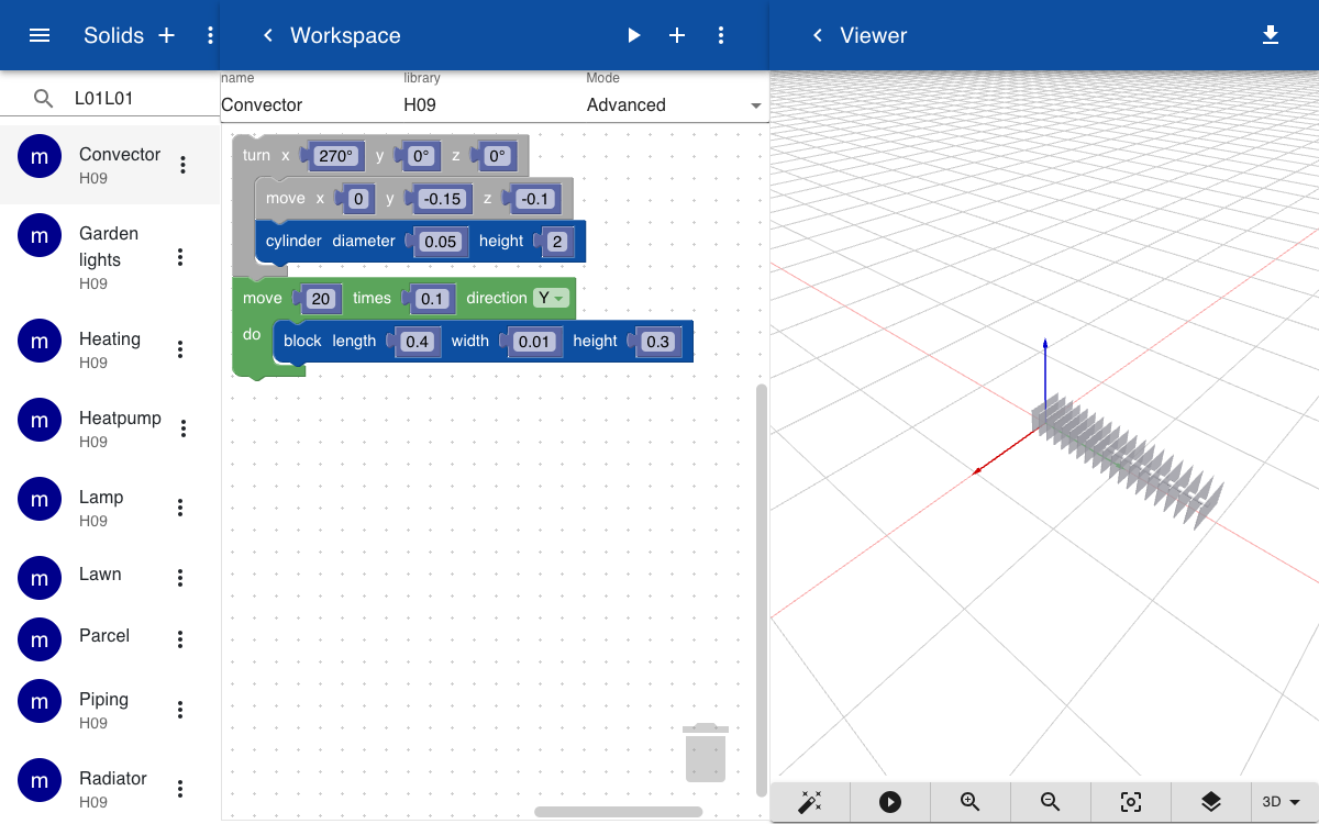
The heating system includes a convector that is placed inside the floor of the living room. The convector is created by repeating a rectangular shape along the Y-axis.
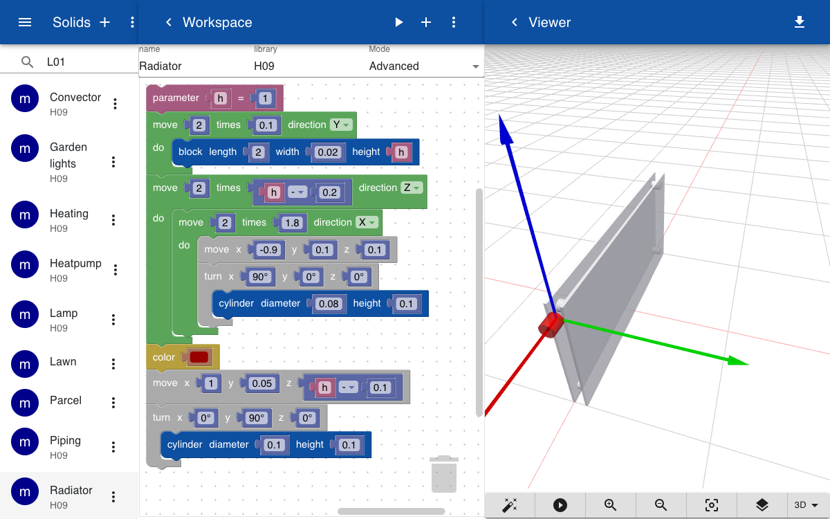
Radiators of different sizes are placed agains the walls. A radiator consists of two plates that are seperated by four cylinders. The part has a variable h, which sets the height of the radiator.
A heat pump, furnace, and fan are created by blocks with a texture mapped on the face that is oriented at the positive Y-axis. The textures are 2D images of the front of the devices in JPG or PNG format.
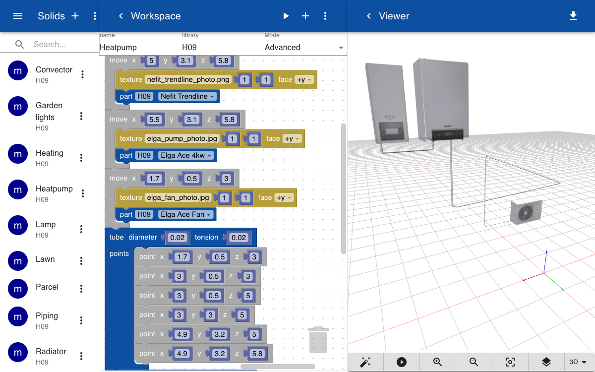
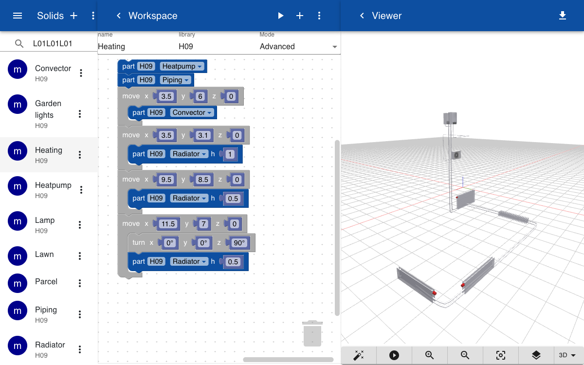
The heating system is created by adding the parts defined above and specify their position in 3D space using the move and turn operations. Three instances of the radiator are added, each with a parameter that sets the height. A set of two tubes is used to connect the radiators and connector with the heatpump and furnace.
Topics
To render the model you have to create a geometry subtopic. The value can either include the name of the solid with an optional list of parameters, or a glTF file. Since there are no parameters in this model we can use the static glTF file. Rendering the glTF file is faster than calling the script which dynamically builds the model.
building.home.heating.geometry = Heating.gltf
building.home.heating.pressure = 1.5
building.home.heating.form = Heating
building.home.heating.photo = elga_pump_photo.jpg
building.home.heating.manual = elga_pump_quickstart.pdf
building.home.heating.installationdate = 2023-08-04
building.home.heating.maintenancedate = 2023-08-04
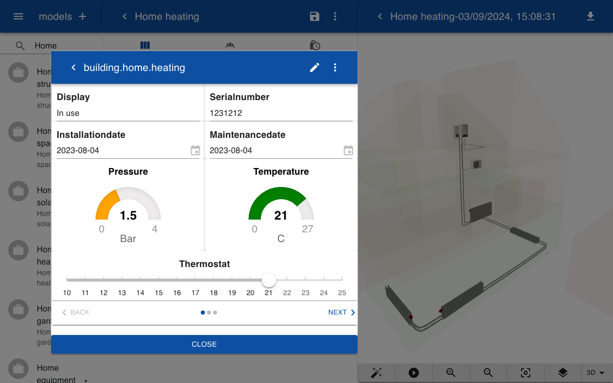
The following topics are automatically set by a connector to the HVAC system using the Home Assistant integration. The temperature, pressure and display parameters are read only. The thermostat sets the desired temperature and can be controller by the user by moving the slider. This is an example of how the digital twin connects with the physical model. If you set the thermostat in the digital twin the room in the house will get warm.
building.home.heating.thermostat = 21
building.home.heating.temperature = 21
building.home.heating.pressure = 1.5
building.home.heating.display = In use
Form
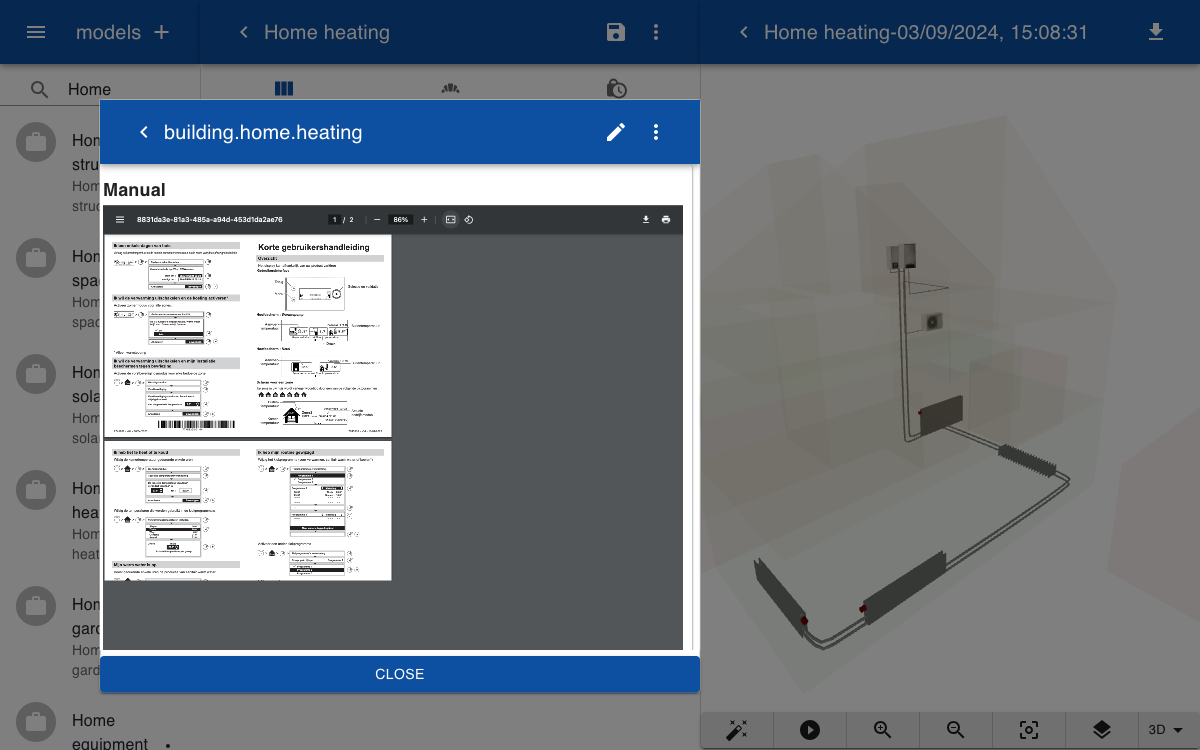
The form to display the real time and life cycle information about the heating system has two pages. The first page shows the sensor values and a slider to control the thermostat. The second page contains a PDF of the user manual.
Heating

Display
|6

Serialnumber
|6

Installationdate
|6

Maintenancedate
|6

Pressure
[0|1:red,1|2:orange,2|3:green,3|4:red 0.0 Bar]

Temperature
[0|15:blue,15|18:yellow,19|21:green,22|27:red 0.0 C]

Thermostat
[10|25 C]

-->

Manual
[document]
Model
The model includes the topics for the structure and heating system. The walls and slabs in the structure are turned off and the slider next to the structure is turned almost fully to the left so that it becomes transparent.
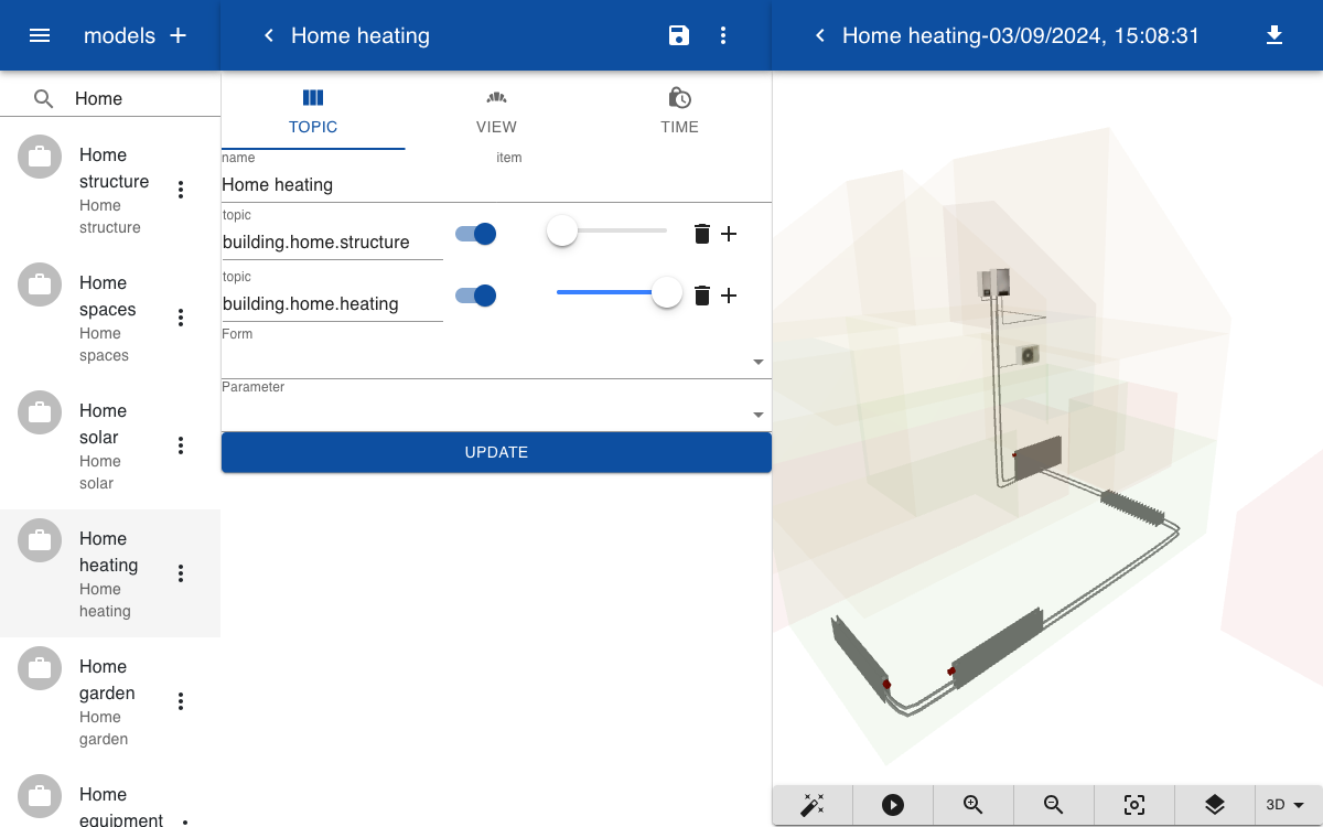
When you click on a part of the heating system the form is opened. You can drag the slider or go to the next page so view the user manual.